


BETAFPV Pavo 20 pro M10 GPS module install
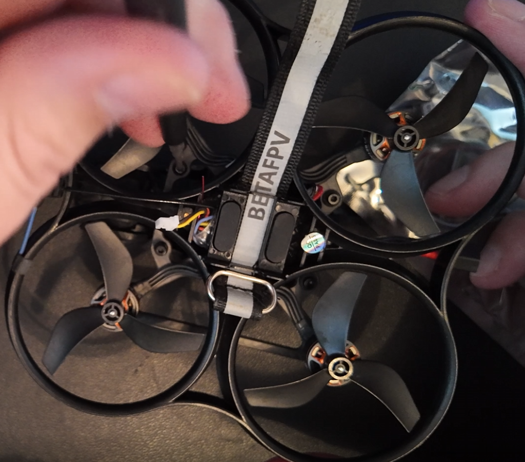
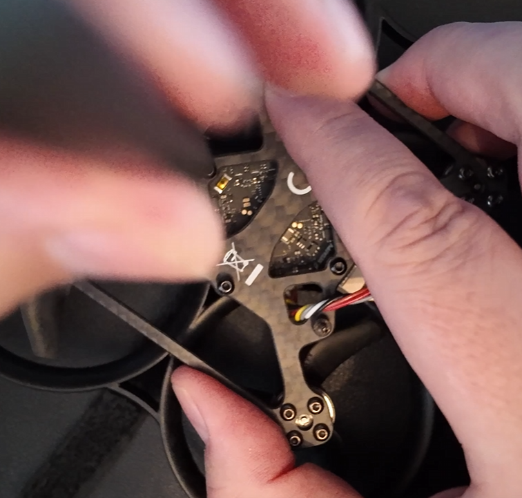
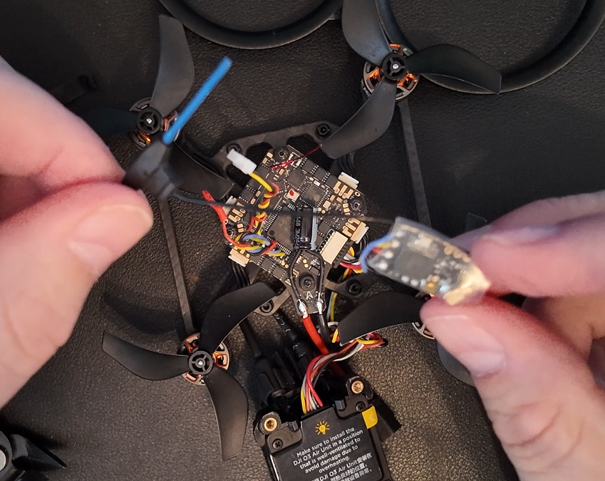
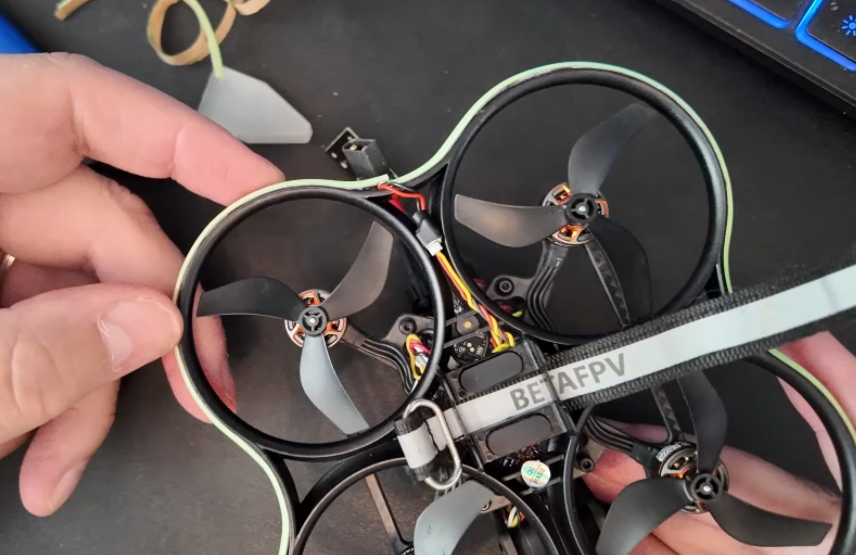
First thing we need todo is flip the quad over and unscrew the 3 screws this will release the airunit and mount on the top of the quad. Secondly remove the 4 screws from the top, this will release the frame from the propellor protection
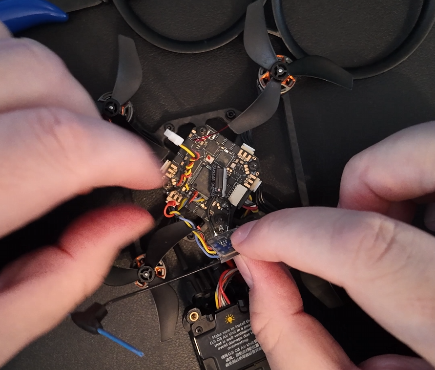
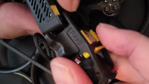
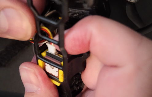
Now i have access to the FC(controller board) i am able to remove the TBS receiver and make the necessary changes to the wiring to allow me to solder the gps wires to the UART1 pads.
That’s the TBS Cables cut. I can now arrange the cables for soldering.
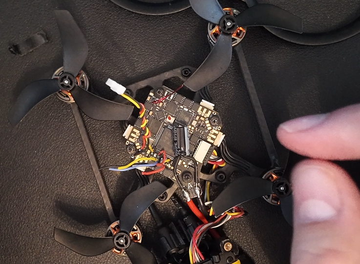
Before we get started we are going to use Uart1. This port had the TBS receiver on there. I am going to cut out the TBS receiver and use it for my GPS module.
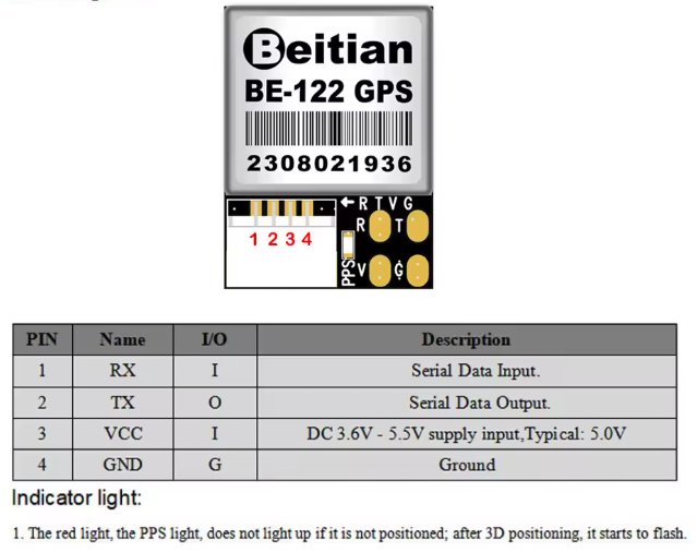
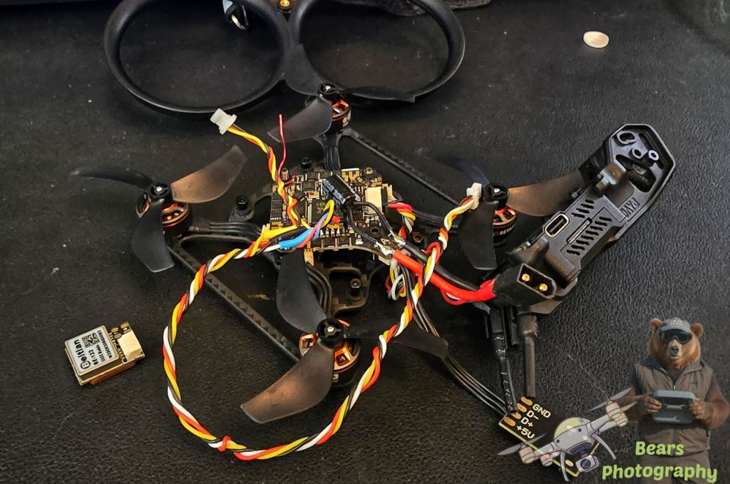
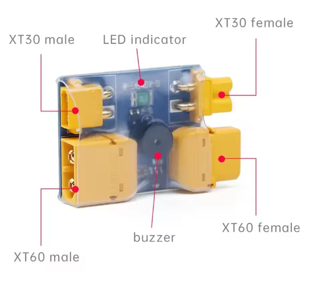
This is the GPS Module i have gone for, Beitian GPS Module BE-122 M10 GNSS GPS.
link here for the module if you want to purchase one
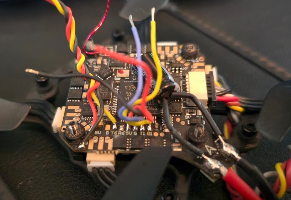
The Picture to the Right you will find G T6 R6 5V G T1 R1 in a row. if you are solder this from new. you will need todo it this way
5V Red wire power
G Ground black
T1 needs to go on RX Yellow
T2 needs togo on TX White
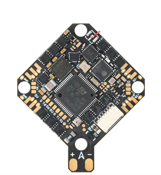
While soldering up the cable make sure there correct to prevent you having todo this again, For me its this
GPS FC
1(Yellow) RX -> TX1(Blue)
2(White) TX -> RX1(Yellow)
3(Red) 5V -> 5V(Red)
4(Black) GND -> GND(Black)
I used a Heat shrink gun, (A lighter is just as good)
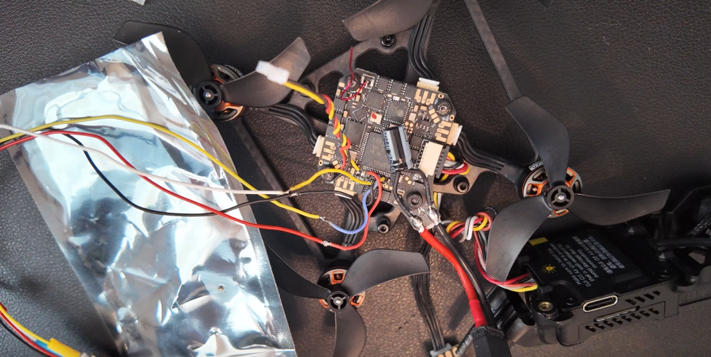
Cables are now soldered and heat shrink used to protect the cables, May Seem a lot of cable, this is so i can place the GPS anywhere i want and if i decided to add the 04 i have plenty of wiggle room.
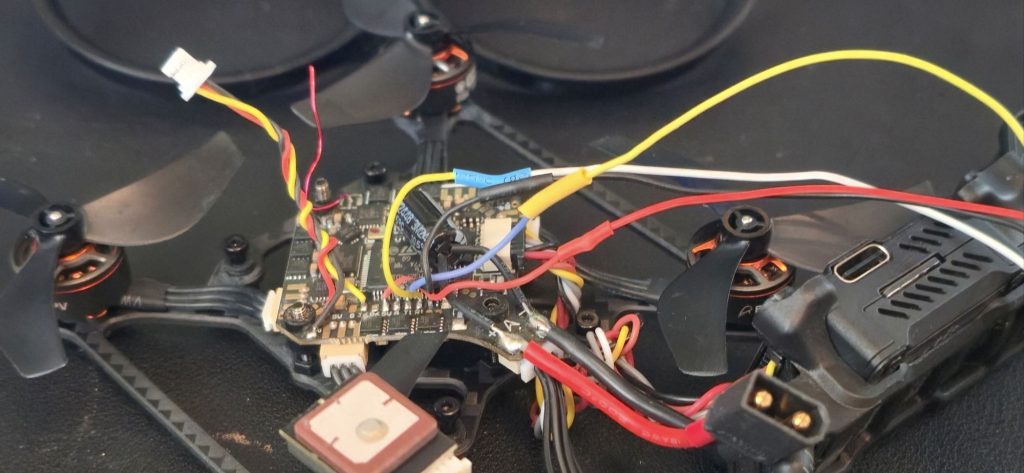

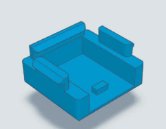
So now the Pavo is back together, The GPS is not in its final resting place, i have got a friend making me a 3d Print holder for it.
before we plug anything back in for testing, use a smoke stopper Link to the one i have is here
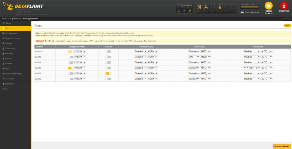
Plug your pavo into USB and loadup Betaflight, Head over to Ports. Now we need to activate the GPS Under Serial Inputs on UART1. Soon as you have done this remember to save.
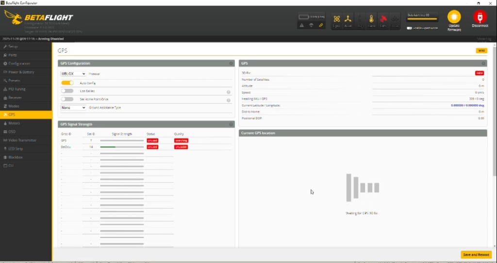
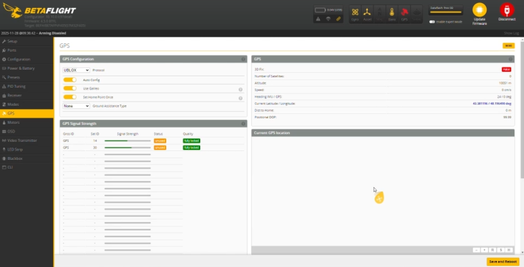
Head over to the GPS tab and wait for those Satellites to lock on. Now we can see this working we can now move onto adding the LEDS Strip. Next stage.
So after Getting the 3D print from my friend, i spent a good 35 minutes trying to place this thing into its resting place, the Problem was a connector was in the way of the air unit, so i decided not to use the 3d print. if you do i suggest you solder the gps so u don’t need to use the Connector plug. click here for the 3D file
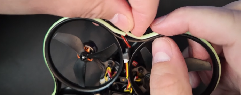
The LED strip was easy to install start at the rear of the quad where the power cable for the LED strip is and work your way around, Snipping of any Excess.
setup remote here LEDS
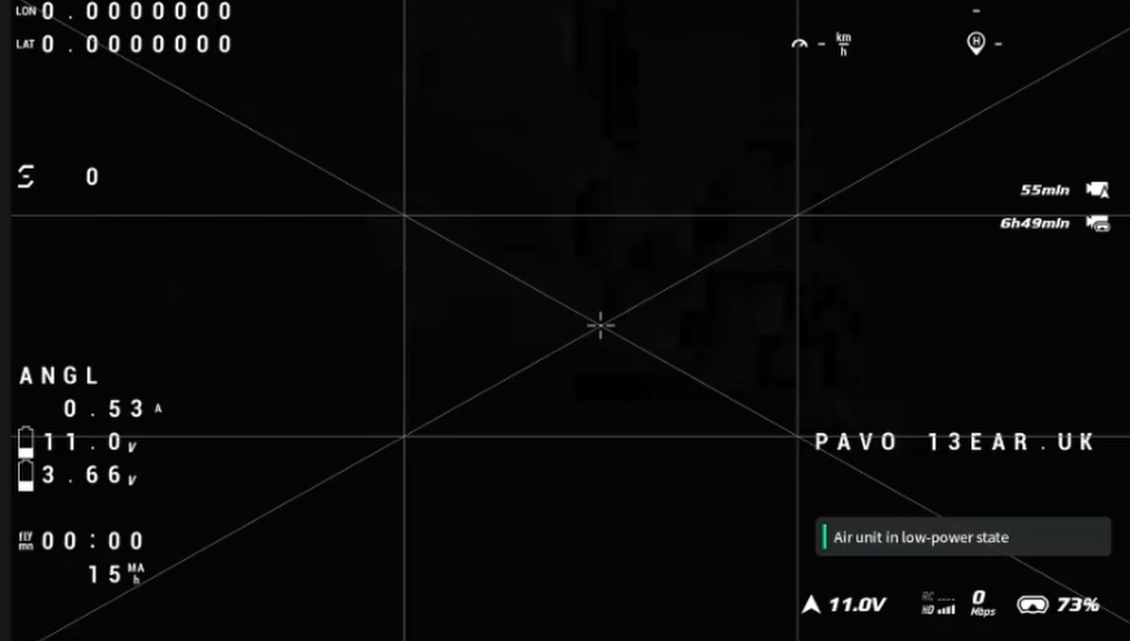
Now we have installed the LED strip and GPS module, We need to add the GPS information to the OSD. Im going to add the Following
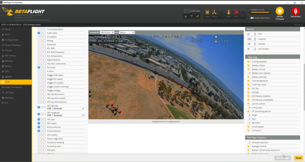
Latitude and longitude to the top left of the screen.
Top right i am going to add GPS Sats, GPS speed, Home direction and Home distance.
Before i go out and try this out with the pavo i thought to try it out on the goggles..
Looks allgood time for some real flying and try her out.